Classes to Tables

--Originally published at Computer Systems Engineering

When you  already have the objects that you want properly designed its time to put them on a relational database. The first thing you need to look at are the data attributes of each class that has to be mapped to zero or more columns depending on your design.


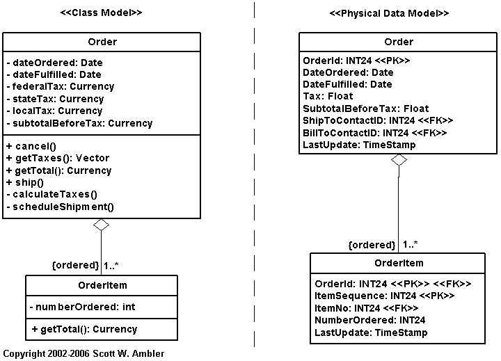
This is an example of how you translate a UML diagram into a data model for a relational database. Overall, the thing you do is put each attribute with its data type and indicate which one will be your primary key. For the attributes that are connected to other classes as well (meaning that they belong to more than one table) you indicate that they are foreign keys. While doing all this process we ignore the methids of the classes, that will come later in the developement of the solution.

A very important aspect you need to take into account while mappingis also inheritance. It can be approached with different techniques according to your program’s structure:

  • Map the entire class hierarchy to a single table: just like the name suggests, it consists in making each attribute of the class into a data object in just one table.
  • Map each class to its own table: with this approach a table is created for each concrete class, each table including both the attributes implemented by the class and its inherited attributes, create one table per class, with one column per business attributes and any necessary identification information.
  • Map the classes into a generic table structure: with this technique you use a generic (meta-data) driven approach.

In the image we can see how different the physical data model can be according to  which method you use to map it. For example, in the pic at Continue reading "Classes to Tables"

UML

--Originally published at Computer Systems Engineering

UML stands for Unified Modeling Language, it is the most known and used modeling language and it consisting of an integrated set of diagrams, developed to help system and software developers for specifying, visualizing, constructing, and documenting the artifacts of software systems, as well as for business modeling and other non-software systems.  It merged together theo object oriented concepts from Booch, OMT and OOSE.

The goal of UML is to provide standarization that can be used for object-oriented design.  UML includes a collection of elements such as Programming Language Statements, Actors (pecify a role played by a user or any other system interacting with the subject), Activities (tasks, which must take place in order to fulfill an operation), Business Process (tasks producing a specific service for customers) and Logical and Reusable Software Components.

UML diagrams can be divided into two categories: Structure diagrams which as their name suggest they represent structural information, and behaviour diagrams that represent functionality of software system and emphasize on what must happen in the system being modeled.

Structure diagrams

  • Class Diagram: represents system class, attributes and relationships among the classes.
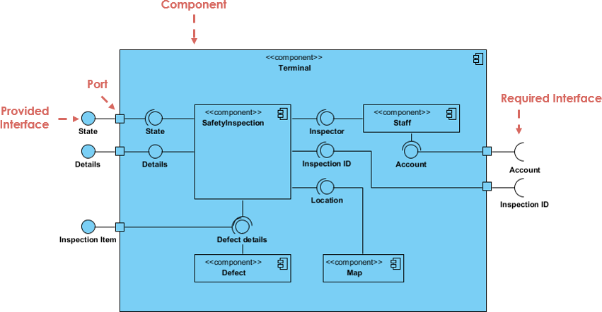
  • Component Diagram: represents how components are split in a software system and dependencies among the components. Component diagrams are essentially class diagrams that focus on a system’s components that often used to model the static implementation view of a system.
  • Deployment Diagram: describes the hardware used in system implementations.
  • Composite Structure Diagram: describes internal structure of classes.
  • Object Diagram: represents a complete or partial view of the structure of a modeled system.
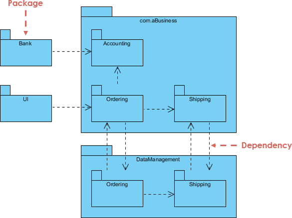
  • Package Diagram: represents splitting of a system into logical groupings and dependency among the grouping.They are containers of multiple UML diagrams and help organize components into groups acording to the relations between them.

Behaviour diagrams

Design Patterns

--Originally published at Computer Systems Engineering

Design patterns are the common solutions to the common problems in software design. You could say that they are a series of rules you can follow if you stump into some inconvenient during your software design process. However, these just provide general solutions to problems so we actually need to learn how to apply them.

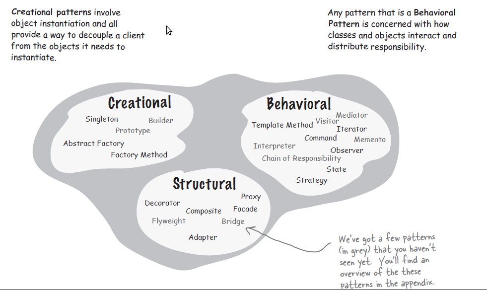
There is a long list of design patterns, each under its due clasification. These are:

Creational Patterns

These reffer to the instantiation of classes and how you do this to avoid duplication of code.

  • Abstract factory: creates an instance of several families of classes. It provides an interface for creating families of related objects without specifying their concrete class.
  • Builder: separates object construction from its representation. This can be used in a way that the same construction processes can create different representations.
  • Factory Method: creates an instance of several derived classes. It is basically an interface that the subclasses adapt to do their own specific tasks.
  • Prototype: a fully initialized instance that can be copied or cloned. It is used when direct creation of an object is costly, creates new objects by copying this prototypical instance.
  • Singleton: a class of which only a single instance can exist.

Structural Patterns

These patterns focus on the composition of classes and objects. With the use of inheritance and interfaces they allow objects to be build in a way that provides new funtionality.

  • Adapter: converts the interface of a class into another interface. This allows a class to work with another one even if it had an incompatible interface.
  • Bridge: separates an object’s interface from its implementation.
  • Composite: composes object intro tree structures to represent hierarchies.
  • Decorator: adds additional responsibilities to an object.
  • Facade: class that represents an entire subsystem.
  • Flyweight: it uses the shared characteristics
    Resultado de imagen para brain loading gif
    Continue reading "Design Patterns"

Modeling Languages and Tools

--Originally published at Computer Systems Engineering

Modeling is an integral part of of the software developement process because it allaws a better understanding of its structure and function.

A modeling language is any graphical or textual computer language that provisions the design and construction of structures and models following a systematic set of rules and frameworks.

tenor (7)

They are basically pseudo-languages that developers like to use to better represent the ideas of the software they are trying to build. The modeling languages can be of two types which are:

  • Graphical modeling

In this type of languages we use diagrams which make use of symbols to represent concepts and lines to represent relationships between these concepts.

Imagen relacionada

This is an example of a modeling language, each symbol represents something according to its shape and the lines have different relationships that you make explicit through text, this way you represent your system graphically which is easier to visualize than just thinking the abstract model  in our heads.

  • Textual Modeling

Textual modeling languages use keywords with parameters or other common terms to make something like pseudo-code.

Resultado de imagen para textual modeling language

You make constructs with text base only instead of using shapes like the graphicla ones. This ones can be harder to read but closer to the reality that you want.


References:

http://ceur-ws.org/Vol-837/paper10.pdf

https://www.techopedia.com/definition/20810/modeling-language

Originality is Overrated

--Originally published at Computer Systems Engineering

Let’s talk about chapter 8 of the book 🙂

FlusteredVastHammerheadbird-size_restricted.gif

In this chapter they talk to you about how the smartest (actually they call it the less stupid) thing you can do when you are building is using others work if they have done it before and had proven it to be a very good solution. That using the OO design principles result in an overall better project in terms of flexibility, maintainability and extensibility.

Those OO principles that they suggest you to use are this ones:

  1. Classes should be open for extension, but closed for modification
  2. Avoid duplicate code by abstracting out things that are common and placing them in a single location
  3. Every object in your system should have a single responsibility, and all the object’s services should be focused on carrying out that single responsibility
  4. Subclasses should be suitable for ther base classes.

Those seem like very good rules to follow.

MNpGOg2.gif

The thing i liked about this chapter is how they tell you that you don’t have to do everything yourself from scratch, use the things that others have done before you that are most likely better than the things you could come up with because it has been worked in for a very long time. This reminded me of numerical methods class where the teacher didn’t minded if we used other people’s programs because this methods are widely used so we were going to find much more better stuff on the internet than us coding from scratch. But what she did wanted was an understanding of how the program worked and that we did. I just think its good to learn how to use other people’s things and learn how to adapt it to what you need according to your problem.

Anyways that is all for today.

Bringing Order To Chaos

--Originally published at Computer Systems Engineering

In this chapter we will see where to start with all the little pieces of our problem. We will discuss about Architecture and some other things that need to be taken into account.

A problem one will face when dividing the big problem into small pieces is that we don’t know where to start with those., thats why we need an architecture. Architecture is the design structure that highlights the most important parts of the app and the relationship between all those parts. It is what help us turn a mess into something ordered and neat.

To build the architecture there are 3 things we should ask to know if something is relevant enough to be part of it:

  1. Is it part of the essence of the system? This are the parts that form the core of the application, without them the program can’t exist.
  2. What the heck does it mean? if you are not sure about what a feature means, focus your attention in it because if you neglect it in the future it will cause you alot more trouble.
  3. How the heck do I do it? This is for the things you have no idea how to do, it is important because this will likely require a lot of effort .

Basically, you need to take into account the core of the application plus the things you are clueless about. It is necesarry to know the problem you are trying to solve in order to differenciate the essence of the app from the other features of it, for example in Whatsapp the most essential part is thet users can comunicate to each other and the features that does that are the core, some additional features are the stories that a user can upload, videocalls, and other things that

😦
Continue reading "Bringing Order To Chaos"

The Cathedral and the Bazaar

--Originally published at Computer Systems Engineering

Well this is a journey of Eric Steven Raymond about the unique software that is Linux and how people work on it.

It might not seem so mindblowing now, but back then the way Linux was being made was surely unique: a lot of people working over the internet, each with it’s own ideas about waht the software should do and everyone is allowed to modify it. Pretty crazy right?

This “# 2 Good programmers know what to write. Great ones know what to rewrite (and reuse).” is so true and most of the times people fail to realize it: your program ain’t  better just because you typed all yourself, you just wasted your time by repeating what was made before because of your own ego of having all the control (i’ve encountered a few people that are like this).

Continuing with the lecture, i also found interesting how he said that you don’t understand the problem untill you implement the first solution. Sometimes we make ourselves think that we need to deploy silver bullets when in fact our solutions need to be constantly improved and sometimes thrown away completely to have a better start.

“# 5 When you lose interest in a program, your last duty to it is to hand it o: to a competent successor”  WOW I never thougt about this but it’s true taht when you lose intrerst in something you just throw it away and forget about it so we must think abput other people that might be interested in it and provide them what we have to save them time and for it’s future developement.

All of it talks about how we should release, release, release. This is to correct our buggs and find other ones with the help of clients faster so

tenor (6).gif
Continue reading "The Cathedral and the Bazaar"

Solving Really Big Problems

--Originally published at Computer Systems Engineering

Let’s discuss Chapter 6 of the book, even if it is a big problem.

In the chapter they address how you are supposed to address big problems and they reveal the greatest of secrets: you do the same as with small problems.

giphy8.gif

It seems obvious but thats just how it is. With bigger problems you just need more information and more software and more everything.

Basically what you need to do is break down your bigger problem into more small problems that you can handle instead of trying to solve everything at once.

A good tool to help with this are, as always use cases. Using use case diagrams we can visualize the things that we need to  do in a better way and start addressing every part of the problem.

We are used to do only programs at a small scale at school but most don’t make super big applications like the ones we have to work on when we leave university. However, if we learn to approach and solve this small problems in a good way we will be able to do  it for bigger stuff.

About the project, i think we are still limiting ourselves because we keep thinking about the way to actually build it instead of focusing on the methodology that we should use to approach the problem.

That was all for this so …

tenor (5).gif

Unified Software Process

--Originally published at Computer Systems Engineering

“The Unified Process fits the general definition of a process: a set of activities that a team performs to transform a set of customer requirements into a software system. However, the Unified Process is also a generic process framework that people can customize by adding and removing activities based on the particular needs and available resources for a project.”  (Scott, K. 2001)

With the previous definition we made clear that it is not just a process, but a framework that can be modified to fit the needs that we have, it is an iterative process that allows an increasing understanding of the problem through refinement each time we go around in the process.

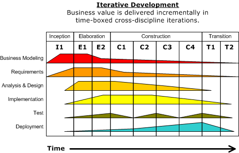
We can visualize the Unified Process as the image below:

Development-iterative


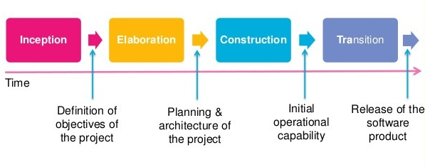
We can see the discilpines like Business Modeling, Requirements, etc. and we also can see the 4 main phases in which it is divided: Inception, Elaboration, COnstruction and Transition. Different amounts of work for each discipline vary depending on which phase of the developement we are in, we can see that symbolized in the image as the area that covers each respective space.

Let’s take a look into each discipline:

  1. Business Modeling: it focuses on understanding the organization and how the way this one works may impact the software that is being developed, taking into account the enterprise rules, mission, vision, organization model, etc.
  2. Requirements: listing the requierements like in any other process but focusing on making them in the form of use cases or UML models.
  3. Analysis and Design: Here we understand and analyze the requirements for the system, define an architecture, conceptualize a prototype and focus on the design of our system.
  4. Implementation: it consists of coding the system, the fun part 🙂
  5. Testing: this focuses on assuring the quality of the software, we
    software-process-models-36-638
    Continue reading "Unified Software Process"

Use Cases

--Originally published at Computer Systems Engineering

Use cases are a tool for organizing system requierements when we want to develope a program. A way to define what a use case is a descripion of all the ways that the user wants to use the system, this way we define the limits of the system by taking into account what the user will be able and will not be able to do.

A use case is different from a requirement definition in the sense that it adds a flow of how the program should work in a specific situation, makin us think beyond and not just on the first step, they make us think of the ways that the program could go wrong in each step of use and make us more cautious about those kind of things. They mark the goals that we should aspire to achieve. We can say that a use case is a diferent scenario for how things could go.

We need to be clear on what should and shouldn’t be included when doing the use cases: we need to think of the user, what type of user is and what is hin/her gonna do in the system, the steps that they will take to fulfill their desires and how the program should respond to those actions. This must not include technical stuff about what programing language to use or the specifics of interfaces.

There are several elements that we need to take into acount when doing use cases:

  1. Actor: the subject that is using the system, the one that performs an action.
  2. Pre-conditions: the things that must be true before the use case runs
  3. Post-conditions: it’s what resulted of the use case
  4. Triggers: the event that causes the use case to iniciate
  5. Main sucess sceanrios: normal path of the use case in
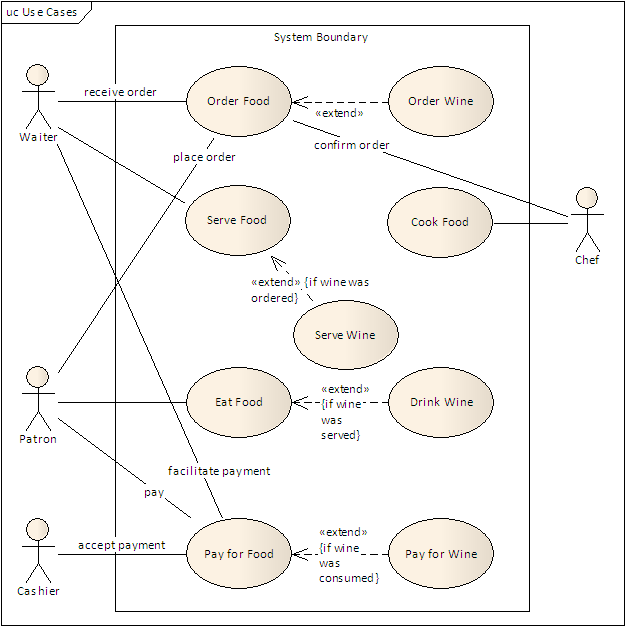
    Restaurant_Model
    Continue reading "Use Cases"