It is fun to stay at the UML

photo1017089474950178736
Dafne Medina, Santiago Kelley & Juan Pablo Ramirez

UML is a standard language for specifying, visualizing, constructing, and documenting the artifacts of software systems. It was created by Object Management Group and UML 1.0 specification draft which was proposed to the OMG in January 1997.

They are standardized diagram types to help you describe and visually map a software system’s design and structure. UML makes it possible to model just about any kind of application, both specifically and independently of a target platform, as it provides elements and components to support the requirement of complex systems, following the object oriented concepts and methodology.

Different diagrams are used for different type of UML modeling. There are three important type of UML modeling: Structural, Behavioral and Architectural.

Structural modeling captures the static features of a system and represents the framework for the system, but it never describes the dynamic behavior of the system.

car_diagram
via GalleryHip

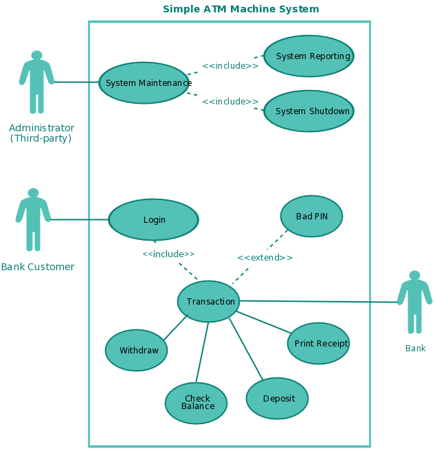
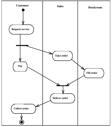
Behavioral model describes the interaction in the system. It represents the interaction among the structural diagrams and shows the dynamic nature of the system.

article-2679990-1f5e589700000578-709_634x333
via DailyMail

Architectural model represents the overall framework of the system. It contains both structural and behavioral elements of the system. Architectural model can be defined as the blueprint of the entire system. Package diagram comes under architectural modeling.

engine-01
via AnimaGraffs

RESOURCES: TutorialsPoint


Unified Modeling Language

When one writes a small project, documentation and standards aren’t that important. But if the number of lines becomes bigger, documentation and standards are a “must”. In the standards, one of the most used is UML.

UML stands for Unified Modeling Language. Its main objective is to maintain an order in big projects. It is focused mainly on object oriented (OO) projects (those build in C#, Java, Ruby…), but it can also work with non OO projects (VB, Javascript…).

UML allows to build:

  • Structure diagrams: class, object, component…
  • Behavior diagrams: use case, activity, state machine…
  • Interaction diagrams: communication, sequence, timing…

UML as itself is not programming. It sets up the bases of the project, but it does not implement the funcionality of it.

flickr photo by yukop https://flickr.com/photos/yukop/7548393976 shared under a Creative Commons (BY-SA) license

Unified Modeling Language (UML)

HISTORY OF UML

        The development of UML began in late 1994 when Grady Booch and Jim Rumbaugh of Rational Software Corporation began their work on unifying the Booch and OMT (Object Modeling Technique) methods. In the Fall of 1995, Ivar Jacobson and his Objectory company joined Rational and this unification effort, merging in the OOSE (Object-Oriented Software Engineering) method.

As the primary authors of the Booch, OMT, and OOSE methods, Grady Booch, Jim Rumbaugh, and Ivar Jacobson were motivated to create a unified modeling language for three reasons. First, these methods were already evolving toward each other independently. It made sense to continue that evolution together rather than apart, eliminating the potential for any unnecessary and gratuitous differences that would further confuse users. Second, by unifying the semantics and notation, they could bring some stability to the object-oriented marketplace, allowing projects to settle on one mature modeling language and letting tool builders focus on delivering more useful features. Third, they expected that their collaboration would yield improvements in all three earlier methods, helping them to capture lessons learned and to address problems that none of their methods previously handled well.

The efforts of Booch, Rumbaugh, and Jacobson resulted in the release of the UML 0.9 and 0.91 documents in June and October of 1996. During 1996, the UML authors invited and received feedback from the general community. They incorporated this feedback, but it was clear that additional focused attention was still required.

A UML is a diagram that includes a collection of elements such as:

  • Programming Language Statements
  • Actors: specify a role played by a user or any other system interacting with the subject.
  • Activities: These are tasks, which must take place in order to fulfill an operation contract. They are represented in activity
    Continue reading "Unified Modeling Language (UML)"

Lenguaje unificado de modelado (UML)

UML es el lenguaje de modelado de los sistemas de software más utilizado en la actualidad.

Es un lenguaje gráfico que nos permite poner un estándar para los sistemas que incluye procesos, funciones del sistema,esquemas de datos, expresiones de lenguaje y compuestos reciclados.

Hay que entender algo en concreto el UML no es una programación estructurada, solo se diagrama la realidad de una utilización en un requerimiento.

La utilización de modelos en nuestro código nos puede abrir los ojos a una gran variedad de posibilidades, aunque nosotros no estamos acostumbrados a su utilización, es muy recomendable que las comprendas ya que las mayorías de los trabajos tienen un cierto modelo que todos los programadores tienen que seguir para que todos puedan entender el código con mayor facilidad y aumente la productividad del equipo.

Algunas ventajas de la utilización de este modelo son:

  • La reutilización de código.
  • Facilitación de mantenimiento y comprensión del código.
  • Mejora la productividad del equipo.

Referencia 1, Referencia 2


Floreth's Blog 2016-10-11 08:43:00

UML diagram

UML stands for Unified Modeling Language. UML is a way of visualizing a software program using a collection of diagrams. Today, UML is accepted by the Object Management Group (OMG) as the standard for modeling software development.

Types of UML diagrams

The current UML standards call for 13 different types of diagrams: class, activity, object, use case, sequence, package, state, component, communication, composite structure, interaction overview, timing, and deployment.
These diagrams are organized into two distinct groups: structural diagrams and behavioral or interaction diagrams.
Structural UML diagrams
  • Class diagram
  • Package diagram
  • Object diagram
  • Component diagram
  • Composite structure diagram
  • Deployment diagram
Behavioral UML diagrams
  • Activity diagram
  • Sequence diagram
  • Use case diagram
  • State diagram
  • Communication diagram
  • Interaction overview diagram
  • Timing diagram
Th most used and important UML diagrams are (:
Sequence Diagram
Sequence diagrams describe interactions among classes in terms of an exchange of messages over time.

Use Case Diagram 
Use case diagrams model the functionality of a system using actors and use cases.


Class Diagram 
Class diagrams are the backbone of almost every object-oriented method, including UML. They describe the static structure of a system.


Object Diagram 
 sometimes referred to as Instance diagrams are very similar to class diagrams. Like class diagrams, they also show the relationship between objects but they use real world examples. They are used to show how a system will look like at a given time. Because there is data available in the objects, they are often used to explain complex relationships between objects.


UML stands for Unified Modelling Language

Born in 1994, UML is a technique for system specification in every phase. Created by Grady Booch, James Rumbaugh, and Ivar Jacobson, it covers all main aspects of previous designing methods. The first version of UML was released in 1997, and it has been successfully used in a number of different systems for different industries. (UNAM, n.d.)

Benefits of using UML:

  • Improves development time
  • Establishes concepts and executables
  • Creates a modelling language used by humans and machines
  • Improves support and control for project management
  • High reuse and reduced costs
  • Models systems using object oriented concepts

Types of UML diagrams

Types of UML diagrams with structure diagrams coming first and behavioral diagrams starting from position 8. Click on any diagram type to visit that specific diagram type’s description (Creately, 2012).

  1. Class Diagram
  2. Component Diagram
  3. Deployment Diagram
  4. Object Diagram
  5. Package Diagram
  6. Profile Diagram
  7. Composite Structure Diagram
  8. Use Case Diagram
  9. Activity Diagram
  10. State Machine Diagram
  11. Sequence Diagram
  12. Communication Diagram
  13. Interaction Overview Diagram
  14. Timing Diagram
uml-diagram-types1

UML diagram types (Creately, 2012)

References:

http://creately.com/blog/diagrams/uml-diagram-types-examples/

http://profesores.fi-b.unam.mx/carlos/aydoo/uml.html


UML

Unified Modeling Language (UML) is not a program language that where you can write code and create something that a computer will understand; but is a way to represent, build or record the elements of an oriented object software.

Modeling is the designing of software applications before coding.”
                                    Says UML.org

In UML you design diagrams that can contain different elements of the software, for example, the most common is the one where you write the name of the class, its attributes and its methods. But it all depends of the diagram you use. In UML there are many different diagrams with different uses and elements that you can write.

Is not necessary to become an expert of UML because is not actually a must for learning actual coding, but is important to know about it because it helps in the design part of software. Creating an UML diagram is like drawing a sketch, is not that important and is unnecessary to put much effort on it, just with understanding the idea is enough.

There are many UML diagrams (13 to be exactly) so in the next section there are only the three most important.

Activity Diagram:

Activity Diagrams are used to design complex methods. It describes phases or activities done by the computer or an user. They are also used to describe business processes in a single usage scenario. They look a lot like flowcharts, actually, activity diagram is an upgraded version of flowcharts. Take a look at this example:
https://farm4.static.flickr.com/3522/3204423336_d1ff94dab3.jpg


flickr photo by jean-louis zimmermann https://flickr.com/photos/jeanlouis_zimmermann/3204423336 shared under a Creative Commons (BY) license

This example describe a generic shop process. As you can see some task are only for a specific agent and reading it is really Continue reading "UML"