UML

Unified Modeling Language (UML) is not a program language that where you can write code and create something that a computer will understand; but is a way to represent, build or record the elements of an oriented object software.

Modeling is the designing of software applications before coding.”
                                    Says UML.org

In UML you design diagrams that can contain different elements of the software, for example, the most common is the one where you write the name of the class, its attributes and its methods. But it all depends of the diagram you use. In UML there are many different diagrams with different uses and elements that you can write.

Is not necessary to become an expert of UML because is not actually a must for learning actual coding, but is important to know about it because it helps in the design part of software. Creating an UML diagram is like drawing a sketch, is not that important and is unnecessary to put much effort on it, just with understanding the idea is enough.

There are many UML diagrams (13 to be exactly) so in the next section there are only the three most important.

Activity Diagram:

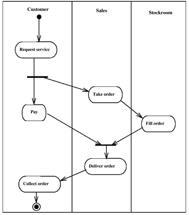
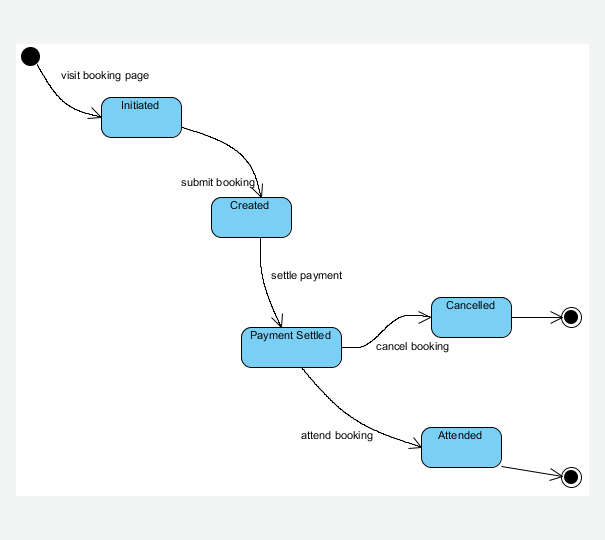
Activity Diagrams are used to design complex methods. It describes phases or activities done by the computer or an user. They are also used to describe business processes in a single usage scenario. They look a lot like flowcharts, actually, activity diagram is an upgraded version of flowcharts. Take a look at this example:
https://farm4.static.flickr.com/3522/3204423336_d1ff94dab3.jpg


flickr photo by jean-louis zimmermann https://flickr.com/photos/jeanlouis_zimmermann/3204423336 shared under a Creative Commons (BY) license

This example describe a generic shop process. As you can see some task are only for a specific agent and reading it is really Continue reading "UML"
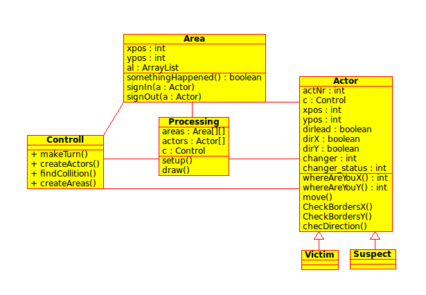
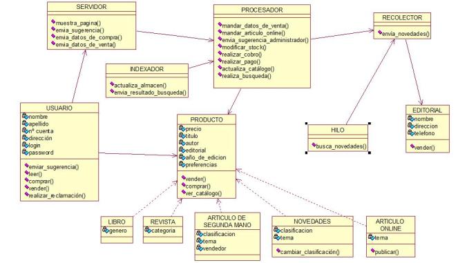
Unified Modeling Language (UML) Types

A UML is a diagram that includes a collection of elements such as:

  • Programming Language Statements
  • Actors: specify a role played by a user or any other system interacting with the subject.
  • Activities: These are tasks, which must take place in order to fulfill an operation contract. They are represented in activity diagrams.
  • Business Process: includes a collection of tasks producing a specific service for customers and is visualized with a flowchart as a sequence of activities.
  • Logical and Reusable Software Components


HISTORY OF UML

        The development of UML began in late 1994 when Grady Booch and Jim Rumbaugh of Rational Software Corporation began their work on unifying the Booch and OMT (Object Modeling Technique) methods. In the Fall of 1995, Ivar Jacobson and his Objectory company joined Rational and this unification effort, merging in the OOSE (Object-Oriented Software Engineering) method.

       As the primary authors of the Booch, OMT, and OOSE methods, Grady Booch, Jim Rumbaugh, and Ivar Jacobson were motivated to create a unified modeling language for three reasons. First, these methods were already evolving toward each other independently. It made sense to continue that evolution together rather than apart, eliminating the potential for any unnecessary and gratuitous differences that would further confuse users. Second, by unifying the semantics and notation, they could bring some stability to the object-oriented marketplace, allowing projects to settle on one mature modeling language and letting tool builders focus on delivering more useful features. Third, they expected that their collaboration would yield improvements in all three earlier methods, helping them to capture lessons learned and to address problems that none of their methods previously handled well.

     The efforts of Booch, Rumbaugh, and Jacobson resulted in the release of the UML 0.9 and 0.

Continue reading "Unified Modeling Language (UML) Types"

UML: The best diagrams

The main purpose of UML is to provide the developer community a common way to design the base of an application. The primary authors were Jim Rumbaugh, Ivar Jacobson, and Grady Booch; which have originally their own methods, but they joined forces to create a better one.

1. Class Diagram

2. Activity Diagram

These diagrams represent the workflow of the process that needs to be described. In other words, it describes the process or actions between two or more classes. The flow starts with a circle and then continues with the actions that are inside rectangles. There are also conditionals represented by a diamond.

c2eme

3. Deployment Diagram

4. Sequence Diagram


UML: The best diagrams

fbee2d22-eec7-45a7-82f4-e67b6d8cb7701. Class Diagram

2. Activity Diagram

3. Deployment Diagram

4. Sequence Diagram

The sequence diagrams are used to show the interactions between objects. Also, they show the order in which these interactions occur. These interactions are shown depending on the situation. There are two ways to represent the sequence diagrams: processes are shown vertically and interactions are represented as arrows.

440px-checkemail-svg


UML: The Best Diagrams

UML stands for Unified Modeling Language which is used in object oriented software engineering. The UML types are divided into two categories which are structure and behavioral diagrams. In this set of blog posts we will describe the best UML useful diagrams that are out there:

1. Class Diagram 

Class diagrams are the most UML diagrams used when modeling application structures. These diagrams are based mainly in building blocks of object oriented solutions that show classes, attributes and operators or methods. When having large systems that have many related classes, these are grouped together in order to create class diagrams. The relations between classes are differentiated with different types of arrows.

class-diagram-example-hasp-licensing-domain

2. Activity Diagram

3. Deployment Diagram

4. Sequence Diagram


UML Developers finally understanding each other.

The Unified Modeling Language or UML for short is a standard graphical notation that is made up of sets of diagrams that illustrate what the software architecture of a certain system looks like, it is easy to read so any developer can take a look at it and have a basic understanding of the project.

The design and structure of the system is modeled with UML, it can be applied to any kind of application, independently of the platform used to build it, it is a tool that helps manage large and complex systems because it brings a clearly visible structure to the architecture and design.

Ola Løvholm - DMSP UML
Ola Løvholm –
DMSP UML

UML’s main purpose it to have a stable and common design language so applications can be build and analyzed by other developers, it is a sort of blueprint to software design and architecture.

One uf the main features is the use-case diagram:
It helps development teams visalize what the functional requirements of a system are and how they are related to each other.

Sources:

The Unified Modeling Language (UML)

An introduction to the Unified Modeling Language

UML (Diagram and methods)

Today we are starting on UML (Unified Modeling Language) different implementation methods.

This topic is about UML with class oriented explanation.

Since UML can be used as Object Oriented, the paradigm is able to be part of the UML envioronment.

Class Diagram:

The next diagram shows the Oriented Object with classes application of the UML:

diagrama-de-clases6
Original at: https://onlineshop09.files.wordpress.com

This diagram is used during the analysis and design of Systems, were the complete information of the concept of the system is involved.

Is important to show the atributes, classes and methods of the entire topology in this diagram, so it can be understood what is the structure of the sytem.

Object Diagram:

http://2.bp.blogspot.com/-sVQ1mcWlbPU/T6HmmdGD1nI/AAAAAAAAAyc/ToyCrK_CTxo/s640/D+de+objetos.gif
Original at: http://2.bp.blogspot.com

This is part of the static view of the system, this is the relation between the methods of the classes, making more suitable to know whom is related with others and what way.

Design Pattern:

Design patterns provide a standard terminology and are specific to particular scenario.

As per the design pattern reference book Design Patterns – Elements of Reusable Object-Oriented Software , there are 23 design patterns. These patterns can be classified in three categories: Creational, Structural and behavioral patterns. We’ll also discuss another category of design patterns: J2EE design patterns.

S.N. Pattern & Description
1 Creational Patterns
These design patterns provides way to create objects while hiding the creation logic, rather than instantiating objects directly using new opreator. This gives program more flexibility in deciding which objects need to be created for a given use case.
2 Structural Patterns
These design patterns concern class and object composition. Concept of inheritance is used to compose interfaces and define ways to compose objects to obtain new functionalities.
3 Behavioral Patterns
These design patterns are specifically concerned with communication between
http://www.tutorialspoint.com/design_pattern/images/factory_pattern_uml_diagram.jpg
https://www.visual-paradigm.com/VPGallery/img/diagrams/State/State-Diagram-Sample.png
Continue reading "UML (Diagram and methods)"

UML Woa!

https://upload.wikimedia.org/wikipedia/en/2/2d/UML_logo.gif
Original at: https://upload.wikimedia.org/wikipedia/en/2/2d/UML_logo.gif

Let´s check what UML means and what we can do with it:

UML helps you specify, visualize, and document models of software systems, including their structure and design, in a way that meets all of these requirements. (You can use UML for business modeling and modeling of other non-software systems too.)

You can model just about any type of application, running on any type and combination of hardware, operating system, programming language, and network, in UML. Its flexibility lets you model distributed applications that use just about any middleware on the market. Built upon  fundamental OO concepts including class and operation, it’s a natural fit for object-oriented languages and environments such as C++, Java, and the recent C#, but you can use it to model non-OO applications as well in.

Things that can help modeling in UML:

Structure Diagrams include the Class Diagram, Object Diagram, Component Diagram, Composite Structure Diagram, Package Diagram, and Deployment Diagram.

Behavior Diagrams include the Use Case Diagram (used by some methodologies during requirements gathering); Activity Diagram, and State Machine Diagram.

Interaction Diagrams, all derived from the more general Behavior Diagram, include the Sequence Diagram, Communication Diagram, Timing Diagram, and Interaction Overview Diagram.

Steps to do UML:

1) Select a methodology: There are many methodologies, each differing in some way or ways from the others. There are many reasons why one methodology may be better than another for your particular project.

2) Select a UML Development Tool: Because most (although not all) UML-based tools implement a particular methodology, in some cases it might not be practical to pick a tool and then try to use it with a methodology that it wasn’t built for. But, some methodologies have been implemented on multiple tools so this is not strictly

3296789176_b916c963a2_o
Continue reading "UML Woa!"