UML is not a program language that where you can write code and create something that a computer will understand; but is a way to represent, build or record the elements of an oriented object software.
“Modeling is the designing of software applications before coding.”
Says UML.org
In UML you design diagrams that can contain different elements of the software, for example, the most common is the one where you write the name of the class, its attributes and its methods. But it all depends of the diagram you use. In UML there are many different diagrams with different uses and elements that you can write.
Is not necessary to become an expert of UML because is not actually a must for learning actual coding, but is important to know about it because it helps in the design part of software. Creating an UML diagram is like drawing a sketch, is not that important and is unnecessary to put much effort on it, just with understanding the idea is enough.
There are many UML diagrams (13 to be exactly) so in the next section there are only the three most important.
Activity Diagram
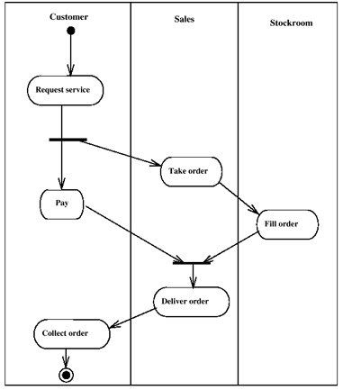
Activity Diagrams are used to design complex methods. It describes phases or activities done by the computer or an user. They are also used to describe business processes in a single usage scenario. They look a lot like flowcharts, actually, activity diagram is an upgraded version of flowcharts. Take a look at this example:
This example describe a generic shop process. As you can see some task are only for a specific agent and reading it is really simple if you already know flowcharts. The diagram starts from the top and tells perfectly who


Class Diagram
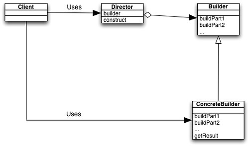
This diagram is used to represent classes and their relationship. They’re represented by using boxes and arrows. Each of the boxes represents a class and the stuff inside it. Most of the time they are broken into three parts: class name, attributes, and methods. Agile Modeling mentions that using this structure means making a design decision and should be avoided if one is only looking for a conceptual model of the class. The arrows are used to represent inheritance and other relationships between classes. Here is an example of a simple class diagram:
Connections between classes may have tags that further explain how the objects will communicate. Some phrases to describe relationships are: lives at, enrolled in, instructs, and on waiting list. These relationships can also contain numbers that specify the amount of objects on each part of the relationship. One Object may hold many instances of another class while those hold even more objects. These numbers help control interactions and how often they should happen.
Class diagrams are among the most popular in UML thanks to the popularity of Object Oriented Programming. It also helps that OOP can be represented in a very understandable and simple way. UML lets developers communicate what a class will do.
Sequence Diagram
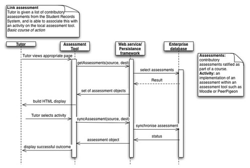
According to Donald Bell in an article for IBM developerWorks, this diagram is used to show in sequential order the interactions between two objects. This diagram is also called event diagrams or event scenarios. The main purpose of a sequence diagram is to define how related event sequences should result in a desired outcome, it models in a graphic way the flow logic of a system and it’s typically used to model usage scenarios and the logic of methods or services.
This kind of diagram is important because it shows the interaction logic between the the objects in the system in the time order that the interactions occur, which makes it specially useful to use to document a system’s requirements and design and it allows people to document and validate their logic.
UML is not a development method, but from there you can create oriented object software with any language that support oriented object programming, just like if they were instructions of how to do something, and the language you use, is the tool to create it.
Wrote by me and:


