
Hey guys it has been a while since the last time that I published anything but I came back to show you guys some cool thing that I have been building for some time now. It isn’t perfect yet but it is a working prototype. Basically what I’m trying to do is build a security system for cars. In the market they are called immobilizers but they ara kind of expensive so I’m made this much more economic one.
So in the video you will see two circuits, one is the transmitter and the other is the receiver. Each circuit consists of 3 parts. In the transmitter circuit we have: an encoder (HT12E), a PIC 16F628A and a radio frequency transmitter. In the receiving circuit we have: a decoder (HT12D), a PIC 16F628A and a radio frequency receiver.
I made of a pattern of numbers that i choose at the beginning of the program. The two circuits work as a pair and if any of them fail then the whole system fails. The flow of information goes like this: first the PIC from the transmitter sends in a loop information to the encoder (HT12E) and then the encoder encrypts the information to then send it to the radio frequency transmitter. After that the radio frequency receiver intercepts it and sends the data to the decoder (HT12D), this decoder deciphers the information and sends it to the PIC on the receiving circuit. If all the information is correct then the pick activates a relay which finally activates the fan. Remember that the fan is just there for demonstration. It can be replaced with anything that needs 12 volts.
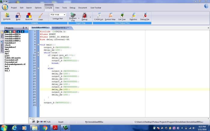
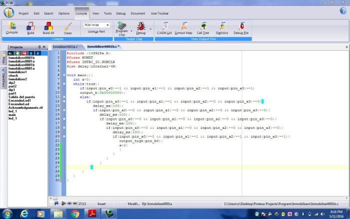 Here is a screenshot of my code. The first image shows the code for the first pic which is on the the transmitter

and the second image is the code for the second pic which is on the receiving circuit. Alright so basically in this code i work with delays and ports. The code is mainly inputs, outputs, conditionals and a loop. The first code sends for pieces of data which are interpreted as 4 different pins either sending a low or high signal in that instance. there is a delay of 100 milliseconds between each of the four instances. I use port a on the PIC as an output and port B as an input. In the first code if the PIC receives an input it sets all of the 4 output pins to high, which will make the fan turn off. For the second code I am constantly reading what it is receiving as an input so that the PIC will know if it needs to turn on the fan or turn it off.
Here is a link and video that I used to make this project possible:
![]()
![]() PROJECT WIRLESS COMUNICATION by Orlando Lara is licensed under a Creative Commons Attribution-ShareAlike 4.0 International License.
PROJECT WIRLESS COMUNICATION by Orlando Lara is licensed under a Creative Commons Attribution-ShareAlike 4.0 International License.