Classes to code

--Originally published at Hackerman's house

If you have read my blog up until now, you should know the basics about software design, and specifically about the use of UML in this area. Let’s see how to take advantage of all the analysis and design we have done. The class design that we already know how to do can be converted into code that will be the actual implementation of the system.

Resultado de imagen para class diagram

The quality of the diagrams used has a direct implication on how to translate it into code. Diagram classes are object oriented, so it may be convenient for you to convert these diagrams into a object oriented language; this will allow you to keep the identity and functionality of the system you design; if you consider that using a non-object oriented language is more appropriate in your own case feel free to do so.

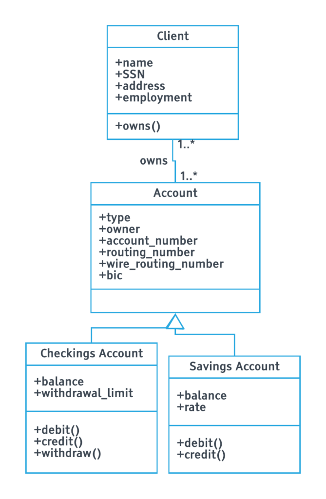
It is important for you to have a profound understanding of your system and your diagrams before starting to code. You will be able to see that the class diagrams offer you a lot of information to that you can take advantage of; the first example is the attributes you will need to initialize in your code. The method’s name gives you a basic understanding of what you have to program. Even the inheritance is specified within the diagrams, all you have to do is implement all the design you already have. Just take your time and select a language you are familiarized with.

Resultado de imagen para coding

As we can see, the hard part is already done when the analysis and design is finished. The implementation is just a translation of what we already know about the system.

Chapter 8 HFOOAD

--Originally published at Hackerman's house

Design principles

This chapter talks about a topic I already discussed a little in one of my posts. Design principles, which are guides that can be used to solve common problems when you are programming and allow you to do better code and without having that many troubles.

Imitation is the sincerest form of not being stupid

A design principle is a basic tool or technique that can be applied to writing code, the principal function of these principles is to make the code more maintainable, flexible or extensible.

The first one that is exposed it is really simple, it is called Open-Closed Principle, the basic idea is that the code should be extensible but not modified. A basic example of this is when you inherit from a class and you override an existing method. The behavior in the original class that is already proven won’t be affected, but it is useful for other similar implementations.
locked

Image by Montillon.a

The Don’t Repeat Yourself Principle has to do with reutilization of code, when you are coding you have to abstract out things that are common and placing those things in a single location. First you need to detect the repeated code and determine which is the best place or class for that specific code. Then you erase the repeated code and just reference the code from the appropriate place. This is directly related to the requirements list, you want to implement each feature just once in the system.

repeat

Photo by Corliss NG

The Single Responsibility Principle. Every object in your system should have only one responsibility. You must analyze the methods inside a class to determine that they belong in there, that they are the responsibility of that specific object. If this isn’t the case, you need to move these

Resultado de imagen para single task
Continue reading "Chapter 8 HFOOAD"

Classes to tables

--Originally published at Hackerman's house

When you have to map objects to relational databases, the place where you have to start is with the data attributes of the class. It is important to define in how many columns these attributes will be mapped, it can be from zero columns to many more. Not all attributes are persistent, this means that they are used for some temporal calculation in the application, this has a direct impact in the way the database is designed because it’s possible that this attribute is not necessary in your database. In the case that an attribute is an object in their own, the attribute will map into several columns in the database.

The easiest mapping is when each attribute goes into a single column. In this case the class model and the physical data model can be very similar; the main differences will be that the data model needs at least one primary key, and in case there are more classes interrelated you need to add the foreign keys for the occasion.

Inheritance

Inheritance is a big deal when mapping a class into a table. The issue is figuring out how to organize the inherited attributes in your model. There are three fundamental solutions for this.

This class hierarchy will be modified using the three approaches.

Figure 1. A UML class diagram of a simple class hierarchy

Using one data entity for an entire class hierarchy.

This means that you will map an entire class hierarchy into just one data entity that contains all the attributes of all the class in the hierarchy. It is important to add the primary key to the data entity. The advantage of this approach is that you have all the information available in just one table; this supports polymorphism in an easy way. The cons are that has a high level of coupling and an error

Figure 2. Mapping the class hierarchy to one single data entity.
Figure 3. Mapping each concrete class to a single data entity.
Figure 4. Mapping each class to its own data entity.
Continue reading "Classes to tables"

UML Part 2

--Originally published at Hackerman's house

As I already discuss in another posts, UML is a common language used to draw diagrams that can express software processes or even business models. In this post I will be talking more about this amazing resource.

State Machine Diagrams

These diagrams are used to describe the states of a component within a system. The name of this type of diagram is state machine because it is a machine that describes multiple states of an object and how it changes due to internal and external events of the system.

UML State machine Diagram

Package Diagrams

A package diagram is a container of multiple UML diagrams. They organize diagrams and components into groups, this according to the relation between them. In more complex systems, package diagrams can be constructed by several package diagrams. The purpose of this type of diagrams is to show the relations between large components of the system, bringing an easier understanding of it.

Component diagrams

Component diagrams can help break down the system into smaller components. These components usually work very different than the others.

lambda architecture

MVC

The model view controller is a style of software architecture that separates the system into three main components. The first one is the model, which is a representation of the data. The view contains the information that the client sees, also contains all the ways the client can interact with the system. The last part is the controller that is an intermediary between the first two, its function is to modify the data according to the interaction given with the client; if the data changes the client must be able to see this in the view.

Reference:

https://tallyfy.com/uml-diagram/#component-diagram

UML Part 1

--Originally published at Hackerman's house

UML stands for Unified Modeling Language. It is one of the most popular process modeling techniques. It represents software components utilizing a diagrammatic representation. It is mainly used because of the easy understanding of the representation. One advantage of UML is that in can be used to represent different types of processes; it is standardized, this means that everyone that learns UML can understand the design of other people, besides this, this language provides with a wide range of features that can improve the readability and efficacy of your project.

UML diagrams can be divided in many categories. I’ll be listing 3 of the more important.

Sequence Diagram

These are probably the most important UML diagrams, and can be used in business application development as well as in computer science. They describe the sequence of messages and interactions between actors and objects, it is characterized because they are represented in a chronological manner. It is used to understand how the system works from start to finish, and how the actors take part in the process.

Sequence UML Diagram

Class diagrams

It is a common diagram because most of the software is Object Oriented. Class diagrams contain classes, attributes and behaviors, this means each class is divided in these 3 fields. The relation between the classes is represented as well in this diagram, inheritance is also depicted in this diagram.

Class UML Diagram

Object diagrams

These diagrams are used to check whether the generic structure of the class diagram works. It is based on the class diagram, but depicts specific objects of the classes created earlier; all the values for the attributes of the object are assigned.

Object UML Diagram

Reference:

https://tallyfy.com/uml-diagram/

Design Patterns

--Originally published at Hackerman's house

Design patterns in programming are like recipes in cooking. They are not the final product, but instructions to obtain your final product in an easier and adequate way. Design patterns are repeatable solutions to common problems that occur in software design. They provide proven development paradigms that can help you prevent issues while developing. One of the advantages of design patterns is that they are so common that they are improved over time, making them more robust and more useful overall.

Design patterns are divided into 3 categories, creational patterns, structural patterns and behavioral patterns.

Creational Design Patterns

Resultado de imagen para creation

These design patterns are about class instantiation.

Abstract factory creates an instance of several families of classes. It provides an interface for creating families of related objects without specifying their concrete class.

Builder separates object construction from its representation. This can be used in a way that the same construction processes can create different representations.

Factory Method creates an instance of several derived classes. It is basically an interface that the subclasses adapt to do their own specific tasks.

Prototype is a fully initialized instance that can be copied or cloned. It is used when direct creation of an object is costly, creates new objects by copying this prototypical instance.

Singleton is a class of which only a single instance can exist.

Structural Design Patterns

Resultado de imagen para structure

These design patterns are about Class and object composition. These patterns are divided into class creation patterns that use inheritance to compose interfaces, object patterns define ways to compose objects to obtain new functionality.

Adapter converts the interface of a class into another interface. This allows a class to work with another one even if it had an incompatible interface.

Bridge separates an object’s interface from its implementation.

Composite; composes object intro tree structures to represent hierarchies.

Resultado de imagen para behavior
Continue reading "Design Patterns"

HFOOAD Chapter 7

--Originally published at Hackerman's house

This chapter is about how sometimes you don’t know where to start a project or how to approach it. This is something that made I felt identified to; it is usual that at the beginning of a project I spend more time looking at the screen and thinking without any idea of how to start, so I think it was useful to read this chapter.

The things in your application that are really important are architecturally significant, and you should focus on them FIRST.

One of the first advices I found useful was that before you start designing the relations between the parts of the systems you need to have these parts or at least the basics. Architecture isn’t just about the relationships; it’s is also about deciding which parts are more important to create them first. This is where the three Q’s of architecture get into the scene; they help you determine which modules are more important.
Q

Photo by Bill Dickinson

Is it part of the essence of the system?

The essence is the most basic idea of what a system does. The easiest way to determine if a part is essential to the system is imagining the system withouth that feature, if you can’t, the feature is most probably essential.

What the heck does it mean?

This idea was somewhat new to me, because I usually start with the part that I can understand easily. In this case the suggestion is start with the features we don’t completely understand. This allows you to avoid risks around this feature. Understanding it from the beginning can mean that you won’t have problems when you are designing the relation with other parts.

Confused

Photo by Thomas Hawk

How the heck do I do it?

This idea is really similar to the one Continue reading "HFOOAD Chapter 7"

HFOOAD Chapter 6

--Originally published at Hackerman's house

Chapter 6 is called My Name is Art Vandelay…I am an Architect, it shows how to use the tools we already know to build bigger programs and handle big problems. To solve these big problems, you must remember the steps, we already learned, making sure that the software does what the customer wants, apply basic object-oriented principles and create maintainable software. Using this knowledge, you can approach the big problem as a group of smaller problems that you can attack individually.
Ball

Photo by Kay Ramslay

In the case that you are working in a big system of software, the analysis becomes even more important. There are more elements in the software, this means the cohesion between all its parts become essential in the creation of good software. A good advice given by the book is that first you have to analyze the individual pieces, and after that you analyze the way the interact with each other.

Just like in the previous chapter the interaction with the client is very important to determine the requirements of the system, and what is the purpose of the software. A new term is introduced Feature, a feature is something big that a system does, usually you must do a series of requirements to complete a feature. This means it is basically a more complex requirement.

Get features from the customer, and then figure out the requirements you need to implement those features

Sometimes you need to know what a system does, but don’t want to get into all the detail that use cases require. This is where you can utilize use case diagrams to see the bigger picture. The diagram consists on the actor that is related to the system, the system, and the use cases inside the system (the use cases are

Resultado de imagen para use case diagram
Continue reading "HFOOAD Chapter 6"

The Cathedral and the bazaar

--Originally published at Hackerman's house

Molavi Bazaar

Photo by Kamyar Adl

The Cathedral and the Bazaar is an essay about the open source software, written by Eric Raymond in 1997. It starts comparing the Cathedral that is a vertical model where there are less developers focused on the product, it is more organized and carefully crafted, in this case the beta was released until the product had achieved certain goals and the product was decent enough. On the other part was Linus Torvalds’s style of development, where everyone can contribute to the software. This style is compared to the bazaar, everyone has different approaches and agendas, the problem of this could be that with so many contributors the production of a stable system might be difficult, but this wasn’t the case; the bazaar style seemed to work well.

Release early and often, delegate everything you can, be open to the point of promiscuity

tux_to_valdisere_05

Photo by Tao Mai

The success of Linux and Open source was thanks to many factors. One that I find very important is that the developers get involved because of their own interests. The case that is presented is that the existing software doesn’t serve them well enough, so they contribute to make it better, this way they can use it in their everyday life.

Every good work of software starts by scratching a developer’s personal itch

One key in the bazaar style is taking advantage of the existing software. Software can be improved and working with others and taking their contributions make your work easier and better. If you want to have contributions it is important to do constant releases, this way your contributors and clients can give you constant ideas and feedback to improve your software. Another thing that caught my attention was that every contributor has their own ideas and their Continue reading "The Cathedral and the bazaar"

Modeling Languages and Tools

--Originally published at Hackerman's house

A modeling language is a graphical or textual computer language that is used to design models of new software or system.

Graphical modeling

Graphical modeling languages use diagrams, symbols and arrows to represent relations, real life concepts or even steps.

The most popular is the Unified Modeling Language (UML) this is also the most popular modeling language in general. Thanks to its popularity there is a lot of software that supports this language.

Another one is the flowchart, is a diagram used to represent an algorithm, workflow or process.

Both of these languages are supported by https://www.draw.io/ 

Textual modeling

The textual modeling languages are formalized natural languages. TMLs have the ability to describe whole software. The language has to be readable, this is really important because is common that the programmer needs feedback from the user, the model needs to be easy to understand. It is also important that it is unambiguous.

Some examples of these languages are, PlantUML that is an adaptation of UML into a text only format. TextUML does not suppose the user knos UML concepts, it requieres a large amount of information about classes and relations. Umple is model-oriented programming, it is integrated in Eclipse IDE.

Writing

Photo by Chris Campbell

References:

Martin, M; Macek, O (2012) On General-purpose Textual Modeling Languages, recovered from: http://ceur-ws.org/Vol-837/paper10.pdf