

--Originally published at Computer Systems Engineering
UML stands for Unified Modeling Language, it is the most known and used modeling language and it consisting of an integrated set of diagrams, developed to help system and software developers for specifying, visualizing, constructing, and documenting the artifacts of software systems, as well as for business modeling and other non-software systems. It merged together theo object oriented concepts from Booch, OMT and OOSE.
The goal of UML is to provide standarization that can be used for object-oriented design. UML includes a collection of elements such as Programming Language Statements, Actors (pecify a role played by a user or any other system interacting with the subject), Activities (tasks, which must take place in order to fulfill an operation), Business Process (tasks producing a specific service for customers) and Logical and Reusable Software Components.
UML diagrams can be divided into two categories: Structure diagrams which as their name suggest they represent structural information, and behaviour diagrams that represent functionality of software system and emphasize on what must happen in the system being modeled.
Structure diagrams
- Class Diagram: represents system class, attributes and relationships among the classes.
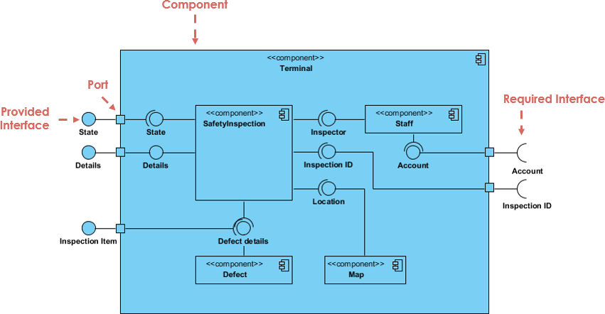
- Component Diagram: represents how components are split in a software system and dependencies among the components. Component diagrams are essentially class diagrams that focus on a system’s components that often used to model the static implementation view of a system.
- Deployment Diagram: describes the hardware used in system implementations.
- Composite Structure Diagram: describes internal structure of classes.
- Object Diagram: represents a complete or partial view of the structure of a modeled system.
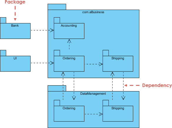
- Package Diagram: represents splitting of a system into logical groupings and dependency among the grouping.They are containers of multiple UML diagrams and help organize components into groups acording to the relations between them.
Behaviour diagrams
- Activity Diagram: represents step by
 workflow of business and operational components.
- Use Case Diagram: describes functionality of a system in terms of actors, goals as use cases and dependencies among the use cases.
- UML State Machine Diagram: represents states and state transition.
- Communication Diagram: represents interaction between objects in terms of sequenced messages.
- Timing Diagrams: focuses on timing constraints.
- Interaction Overview Diagram: provides an overview and nodes representing communication diagrams.
- Sequence Diagram: represents communication between objects in terms of a sequence of messages.
MVC
The Model-View-Controller is an architectural pattern used to develope user interfaces that divides the aplications into three parts that are:
- Model: represents the logical structure of data in a software application and the high-level class associated with it. This object model does not contain any information about the user interface.
- View : collection of classes representing the elements in the user interface (all of the things the user can see and respond to on the screen, such as buttons, display boxes, and so forth)
- Controller: represents the classes connecting the model and the view, and is used to communicate between classes in the model and view.
GRASP
General Responsibility Assignment Software Principles (GRASP) help guide the software design by clearly outlining WHO does WHAT. Which object or class is responsible for what action or role and helps us define how classes work with one another. The key point of GRASP is to have efficient, clean, understandable code.
There are 9 principles:
References:
https://www.visual-paradigm.com/guide/uml-unified-modeling-language/what-is-uml/
https://tallyfy.com/uml-diagram/
https://whatis.techtarget.com/definition/model-view-controller-MVC
https://www.techopedia.com/definition/3243/unified-modeling-language-uml