
--Originally published at Computer Systems Engineering
Testing in OO
--Originally published at Computer Systems Engineering
Verification and Validation
--Originally published at Computer Systems Engineering
Code Revision
--Originally published at Computer Systems Engineering
Classes to code
--Originally published at Computer Systems Engineering
We have invested all those time into making those diagrams but now how do we transform them into code?
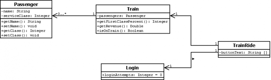
Imagine we have our uml diagram that we want to make into java code:

We need to create those classes that we stated that we had, in this case we have 4 of them: Passenger, Train, TrainRide and Login. Each have their attibutes that we need to add to the class, plus the methods that we thought each of them should have. THen we alsoneed to consider the type of relationship each class have with one another, it could be a relation of composition or aggregation or some other type of relationship, all that we should correctly translate into the code, making a class an interface, the parent/son of another or just make it a normal class.
This is why we should thrive for better diagrams, if we make the perfect diagram then when we translate it, it will inevitably be good code because it has been well thought through, all the attributes are the right data type, they are all the necesary ones, the methods belong to the class that will hold them and also all the relationships in between the clases are the necesary ones to have comunication inside our program in the most logical and eficient way without compromising the independency of each component (that each class modifies its own attibutes and calls it’s own methods and not the other ones).
References:
Putting it all together

--Originally published at Computer Systems Engineering
Finally, we are at the last chapter of the book.

This is what we’ve been waiting for, the moment we put all those pices together to make it all part of a single thing. For this we have had followed this developing process:
- Make sure that your software does what the client wants: here we do the feature list, use cases diagrams, break up the project and list the requirements.
- Apply OOP principles to add flexibility: includes domain analysis, preliminary design, and everything to delimit the problem
- Strive for mantainable and reusable design: this is when we implement the solution and we have to make sure we have an order and clear documentation for when we want to add features, update or whatever we need.
When we were thinking about the project i have to admit that sometimes we were to caught up in what we wanted the program to be that we didn’t stop and think what a customer might want/expect from something like that, so we needed to step back and consider the design process, do it in order to have in mind the customer before the program (i think that’s why we had trouble with the use cases in the delivery of the first partial).
The thing that i learned is that we need to follow like a timeline process and, if it is needed, iterate though it to refine everything and define new things that we might have not considered before. So in conclusion it’s everything about ORDER.

The software is still for the customer

--Originally published at Computer Systems Engineering
Let’s talk about chapter 9 of the book.
Just the title of the chapter speaks so much: how many thimes they ask us for something and in the process we think about some modifications that we think will make it better and forgot what we were asked to do in the first place. I have had this kingo of thought when i had to help build a web page for some people, they gave us the designs and we were just supposed to make it look like that but honestly their designs were find of ugly to me so i had to keep reminding to myself that that’s what they asked me to do and that I should just stick to it.

They talk about how we must think about the user while we build our program, to think all the use cases we can with no limits, to be creative and expect everything to avoid a situation in which out program doesn’t work because we didn’t thought about something that the customer might do. For every scenario that we think of we must make our program work for it, guiding the user to what the right path is in case they make an unexpected action, and that the expected uses work perfectly.
Also, what called my attention is how they say that yeah, all that OO principles and practices that you use to build your program are very helpfull to you and makes things clearer and all but at the end of the day the customer doesn’t care at all about that, they just want you to deliver something that works and solves their problem. That’s why we must think about the client ALL through the process.
Anyways, that is all, enjoy a good song for the morning:
Classes to code
--Originally published at Hackerman's house
If you have read my blog up until now, you should know the basics about software design, and specifically about the use of UML in this area. Let’s see how to take advantage of all the analysis and design we have done. The class design that we already know how to do can be converted into code that will be the actual implementation of the system.
The quality of the diagrams used has a direct implication on how to translate it into code. Diagram classes are object oriented, so it may be convenient for you to convert these diagrams into a object oriented language; this will allow you to keep the identity and functionality of the system you design; if you consider that using a non-object oriented language is more appropriate in your own case feel free to do so.
It is important for you to have a profound understanding of your system and your diagrams before starting to code. You will be able to see that the class diagrams offer you a lot of information to that you can take advantage of; the first example is the attributes you will need to initialize in your code. The method’s name gives you a basic understanding of what you have to program. Even the inheritance is specified within the diagrams, all you have to do is implement all the design you already have. Just take your time and select a language you are familiarized with.

As we can see, the hard part is already done when the analysis and design is finished. The implementation is just a translation of what we already know about the system.
Classes to Tables
--Originally published at Computer Systems Engineering
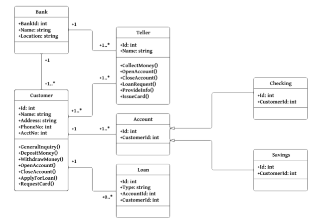
When you already have the objects that you want properly designed its time to put them on a relational database. The first thing you need to look at are the data attributes of each class that has to be mapped to zero or more columns depending on your design.

This is an example of how you translate a UML diagram into a data model for a relational database. Overall, the thing you do is put each attribute with its data type and indicate which one will be your primary key. For the attributes that are connected to other classes as well (meaning that they belong to more than one table) you indicate that they are foreign keys. While doing all this process we ignore the methids of the classes, that will come later in the developement of the solution.
A very important aspect you need to take into account while mappingis also inheritance. It can be approached with different techniques according to your program’s structure:
- Map the entire class hierarchy to a single table: just like the name suggests, it consists in making each attribute of the class into a data object in just one table.
- Map each class to its own table: with this approach a table is created for each concrete class, each table including both the attributes implemented by the class and its inherited attributes, create one table per class, with one column per business attributes and any necessary identification information.
- Map the classes into a generic table structure: with this technique you use a generic (meta-data) driven approach.

In the image we can see how different the physical data model can be according to which method you use to map it. For example, in the pic at Continue reading "Classes to Tables"
UML

--Originally published at Computer Systems Engineering
UML stands for Unified Modeling Language, it is the most known and used modeling language and it consisting of an integrated set of diagrams, developed to help system and software developers for specifying, visualizing, constructing, and documenting the artifacts of software systems, as well as for business modeling and other non-software systems. It merged together theo object oriented concepts from Booch, OMT and OOSE.
The goal of UML is to provide standarization that can be used for object-oriented design. UML includes a collection of elements such as Programming Language Statements, Actors (pecify a role played by a user or any other system interacting with the subject), Activities (tasks, which must take place in order to fulfill an operation), Business Process (tasks producing a specific service for customers) and Logical and Reusable Software Components.
UML diagrams can be divided into two categories: Structure diagrams which as their name suggest they represent structural information, and behaviour diagrams that represent functionality of software system and emphasize on what must happen in the system being modeled.
Structure diagrams
- Class Diagram: represents system class, attributes and relationships among the classes.
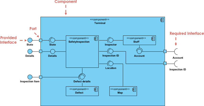
- Component Diagram: represents how components are split in a software system and dependencies among the components. Component diagrams are essentially class diagrams that focus on a system’s components that often used to model the static implementation view of a system.
- Deployment Diagram: describes the hardware used in system implementations.
- Composite Structure Diagram: describes internal structure of classes.
- Object Diagram: represents a complete or partial view of the structure of a modeled system.
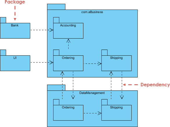
- Package Diagram: represents splitting of a system into logical groupings and dependency among the grouping.They are containers of multiple UML diagrams and help organize components into groups acording to the relations between them.
Behaviour diagrams
- Activity Diagram: represents step by
 Continue reading "UML"